
Views: 2 Author: Site Editor Publish Time: 2026-08-11 Origin: Site
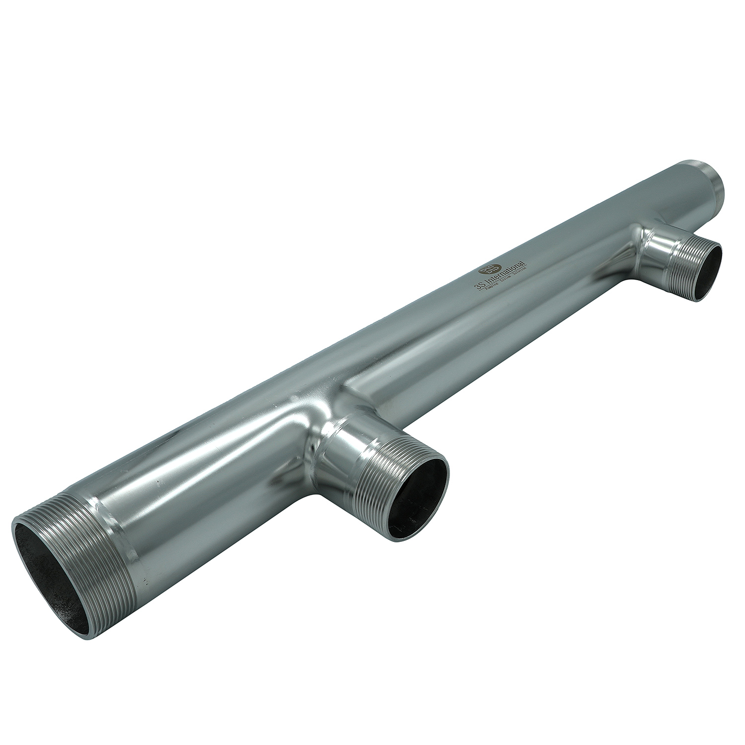
The arrangement of components on a manifold affects everything from pressure drop to maintenance accessibility. Strategic layout design reduces installation complexity, simplifies servicing, and improves overall system reliability.
Key Layout Principles
1. Separate High-Wear Components for Accessibility
Cartridge valves require periodic service. Place high-maintenance components where they can be accessed without disassembling other parts of the manifold. For example, relief valves and solenoid valves should be positioned at the periphery rather than buried in the center -.
2. Group Related Functions Together
Grouping related valves reduces internal passage length and complexity:
| Function Group | Recommended Location |
|---|---|
| Pressure control | Near supply port |
| Directional control | Central positions |
| Flow control | Near actuator ports |
| Instrumentation | Gauge ports (periphery) |
3. Provide Adequate Clearance for Tools
One of the most commonly forgotten elements of manifold selection is spacing between ports. When selecting a manifold, ensure control valves or fittings can be installed without interfering with neighboring components .
Minimum spacing guidelines:
1/8" ports: 0.75" - 1.0" center-to-center
1/4" ports: 1.0" - 1.25" center-to-center
3/8" ports: 1.25" - 1.5" center-to-center
1/2" ports: 1.5" - 2.0" center-to-center
4. Consider Future Expansion
Specify blanking plates on unused stations to allow future valve addition without system modification. Blanking plates serve multiple purposes:
Temporary bypass for failed valve isolation
Configuration changes without replacement
Protection of unused ports from contamination -.
5. Place Instrumentation for Access and Accuracy
Instrumentation-ready designs incorporate:
Pre-tapped ports for pressure transmitters and gauges
Thermowell pockets for temperature measurement
Sample ports for fluid analysis
Mounting platforms for flow meters -.
Layout Considerations for Hydraulic vs. Pneumatic Systems
| Consideration | Hydraulic | Pneumatic |
|---|---|---|
| Component density | Higher (more valves) | Lower (simpler circuits) |
| Clearance requirements | Larger (heavy components) | Smaller (light components) |
| Heat generation | Significant | Minimal |
| Maintenance frequency | Higher (wear parts) | Lower |
| Leak consequence | Higher (environmental) | Lower |
Design Methodology for Complex Manifolds
For complex manifold blocks with both plate valves and cartridge valves, the layout must consider both external component positioning and internal flow path design. Empirical knowledge and rules from engineering standards, technical specifications, and long-term engineering practice guide optimal layout decisions. When layout is based on documented and experiential knowledge, it reduces subsequent path planning complexity, installation difficulty, and maintenance challenges .
3S International Layout Engineering:
Our engineers consider serviceability as a primary design criterion. Component placement is optimized for:
Tool access during installation
Valve replacement without disturbing adjacent components
Clear labeling and identification
Efficient internal flow routing
Layout Consultation: Submit your valve configuration, space constraints, and maintenance access requirements. Receive a recommended layout with clear dimensioning and service access verification.

 FEEDBACK